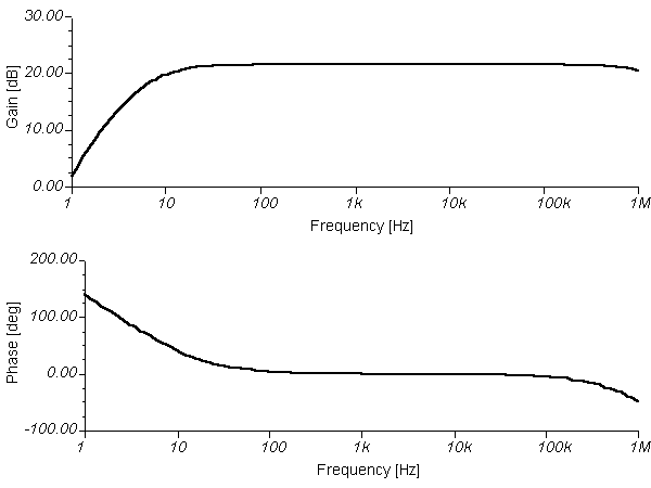
Circuit DescriptionThe amplifier operates in Class AB mode; the single 470R preset resistor controls the quiescent current flowing through the BD139/140 complimentary output transistors. Adjustment here, is a trade-off between low distortion and low quiescent current. Typically, under quiescent conditions, standby current may be 15 mA rising to 150 mA with a 50 mV input signal. A simulated frequency response is shown below: The circuit is DC biased so that the emitters of the BD139 and BD140 are at approximately half supply voltage, to allow for a maximum output voltage swing. All four transistors are direct coupled which ensures:-(i) A good low frequency response(ii) Temperature and bias change stability.The BC109C and 2N3906 operate in common emitter. This alone will provide a very high open loop gain. The output BD139/140 pair operate in emitter follower, meeting the requirements to drive low impedance speakers. Overall gain is provided by the ratio of the 22k and 1k resistor. A heat sink on the BD139/140 pair is recommended but not essential, though the transistors will run 'hot' to the touch.
 The circuit is DC biased so that the emitters of the BD139 and BD140 are at approximately half supply voltage, to allow for a maximum output voltage swing. All four transistors are direct coupled which ensures:-(i) A good low frequency response(ii) Temperature and bias change stability.The BC109C and 2N3906 operate in common emitter. This alone will provide a very high open loop gain. The output BD139/140 pair operate in emitter follower, meeting the requirements to drive low impedance speakers. Overall gain is provided by the ratio of the 22k and 1k resistor. A heat sink on the BD139/140 pair is recommended but not essential, though the transistors will run 'hot' to the touch.
